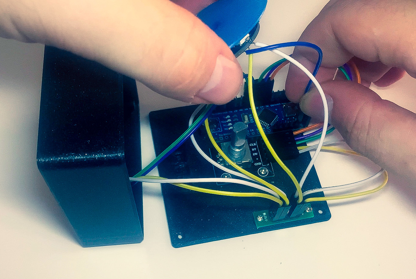
Volume Knob For Aftermarket Head Units Using A Rotary Encoder And Arduino

Volume Knob For Aftermarket Head Units Using A Rotary E Github location for code and wiring diagrams: github cruisinggeek headunitvolumeknobrotary encoders amazon dp b07dm2ymt4?psc=1&ref=. About. putting this arduino module between your aftermarket android head unit with a rotary encoder allows volume control via the knob. requires 2 n channel mosfets to be driven from the arduino pro micro.

Volume Knob Hackaday Hi everyone, i have a touch screen radio in my truck that has no physical knob to adjust the volume, one of these days i swear i will die trying to adjust it using the touch screen. the radio runs android, so i figured i could use a rotary encoder to send volume up and down keys through the arduino as an hid, this worked however not exactly how i thought it would. turns out, my android radio. From the above circuit diagram you can see that the rotary encoder is connected to arduino as the power pins vcc and gnd of encoder are connected to 5v and gnd of arduino respectively, the output pins clk and dt are connected to digital pin6 and digital pin 7 respectively. as we are using an lcd display with i2c adapter, it has only 4 pins. Step by step instructions. connect the rotary encoder to the breadboard. place the two 10 kΩ resistors r1 and r2 from a and b to 5v. place the two 10 kΩ resistors r3 and r4 from a and b to the arduino digital pins 10 and 11, respectively. place the 0.1uf capacitors (c1 and c2) as shown in the schematic to debounce the encoder signal. Connect the a pin of the encoder to the digital pin 2 of the arduino. connect the b pin of the encoder to the digital pin 3 of the arduino. connect the common ground pin of the encoder to the gnd of the arduino. in the arduino code, the state of the a and b pins is continuously monitored.

Rotary Encoder For Dummies For Arduino Raspberry Pi Step by step instructions. connect the rotary encoder to the breadboard. place the two 10 kΩ resistors r1 and r2 from a and b to 5v. place the two 10 kΩ resistors r3 and r4 from a and b to the arduino digital pins 10 and 11, respectively. place the 0.1uf capacitors (c1 and c2) as shown in the schematic to debounce the encoder signal. Connect the a pin of the encoder to the digital pin 2 of the arduino. connect the b pin of the encoder to the digital pin 3 of the arduino. connect the common ground pin of the encoder to the gnd of the arduino. in the arduino code, the state of the a and b pins is continuously monitored. A rotary encoder is an electromechanical device that converts rotational movement into an electrical signal. it measures the rotation and position of a shaft or knob. there are two main types: incremental encoder: which generates pulses to measure relative change. Step 1: wiring. connect the rotary encoders module to the arduino board as follows: connect the module’s clk (clock) pin to a digital pin on the arduino (e.g., d2). connect the module’s dt (data) pin to another digital pin on the arduino (e.g., d3). connect the module’s sw (switch) pin to a digital pin on the arduino (e.g., d4).

Control Rotary Encoder Knob Using Stmicroelectronics Nucleo Board A rotary encoder is an electromechanical device that converts rotational movement into an electrical signal. it measures the rotation and position of a shaft or knob. there are two main types: incremental encoder: which generates pulses to measure relative change. Step 1: wiring. connect the rotary encoders module to the arduino board as follows: connect the module’s clk (clock) pin to a digital pin on the arduino (e.g., d2). connect the module’s dt (data) pin to another digital pin on the arduino (e.g., d3). connect the module’s sw (switch) pin to a digital pin on the arduino (e.g., d4).

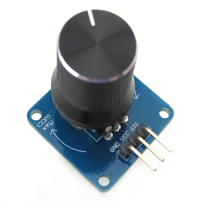
Arduino Knob Switch Rotary Angle Sensor Module

Comments are closed.