Hvac Primary Secondary Circuits

Hvac Primary Secondary Circuits Youtube The primary and secondary circuits are connected via a pipe known as the “low loss header” it is also sometimes referred to as the “decoupler” or “common header”. the primary water flows into this to provide heated or chilled water to the secondary circuits. when the building is at maximum load and is demanding 100% of the system. In this video we take a look at the primary and secondary circuits in a typical centralised hvac heating or cooling system within a commercial building. we l.

Primary And Secondary Circuits In Centralised Hvac Systems The To do that, we’re going to start with the humble piping tee and a concept known as the “tee law.”. the tee law simply states that what goes in the opening (s) of the tee must come out the remaining opening (s). in other words, if you’ve got 150 gpm going into the tee, you’re going to have 150 gpm exiting the tee. Primary secondary a primary secondary pumping scheme divides the chilled water system into two distinct circuits that are hydraulically separated by a de coupler (neutral bridge). in primary secondary systems, chilled water flows through the chiller primary loop at a constant flow rate, whereas in the secondary loop, flow rate is varied. Foolproof method for installing primary secondary . circuits. 7. more than 60 years later, primary secondary pump ing continues to provide the same advantages, but at a higher rate when used with today’s evolving equip ment. the growing popularity of condensing and other modern boilers has made the use of primary secondary piping more important. Primary secondary tertiary pumping. in a primary secondary tertiary system (figure 3), things start to get a bit more complicated, but the principles are all the same. the common pipe (whether it is between the primary loop and the secondary loop, or the secondary loop and the tertiary loop) acts as the decoupler, so flows act independently of one another and there is extra degree of thermal.

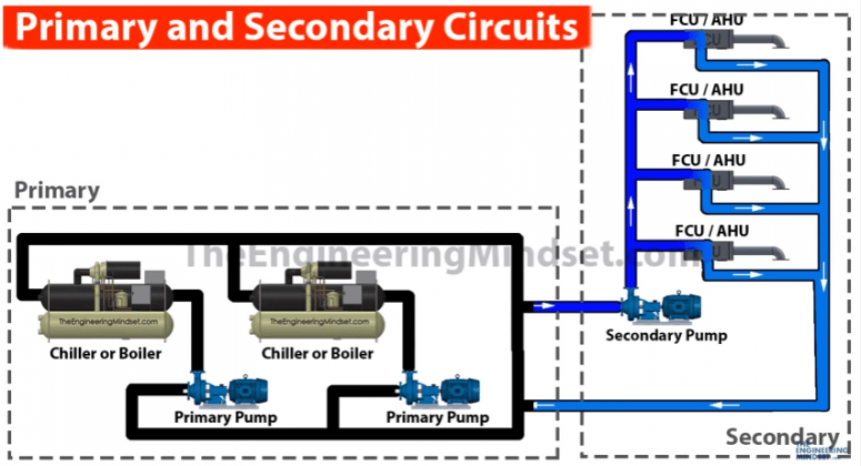
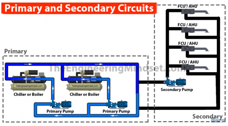
Primary And Secondary Circuits In Centralised Hvac Systems The Foolproof method for installing primary secondary . circuits. 7. more than 60 years later, primary secondary pump ing continues to provide the same advantages, but at a higher rate when used with today’s evolving equip ment. the growing popularity of condensing and other modern boilers has made the use of primary secondary piping more important. Primary secondary tertiary pumping. in a primary secondary tertiary system (figure 3), things start to get a bit more complicated, but the principles are all the same. the common pipe (whether it is between the primary loop and the secondary loop, or the secondary loop and the tertiary loop) acts as the decoupler, so flows act independently of one another and there is extra degree of thermal. The primary secondary pumping diagram is a schematic representation of the flow of water in a hydronic hvac system. it helps to illustrate how the system is structured and how water is distributed between the primary and secondary loops. the primary loop contains the main pump, which is responsible for circulating the water through the system. In a primary secondary hvac pumping system, 2 hydraulically separate chilled water circuits are present. the primary circuit has low head primary pumps which typically maintain a constant flow rate through chillers. the secondary circuit has high head secondary pumps which maintain flow through loads (ahus, fcus, etc). secondary pumps are.

Primary And Secondary Circuits In Centralised Hvac Systems Hvac The primary secondary pumping diagram is a schematic representation of the flow of water in a hydronic hvac system. it helps to illustrate how the system is structured and how water is distributed between the primary and secondary loops. the primary loop contains the main pump, which is responsible for circulating the water through the system. In a primary secondary hvac pumping system, 2 hydraulically separate chilled water circuits are present. the primary circuit has low head primary pumps which typically maintain a constant flow rate through chillers. the secondary circuit has high head secondary pumps which maintain flow through loads (ahus, fcus, etc). secondary pumps are.

Primary And Secondary Circuits In Centralised Hvac Systems

Comments are closed.