Guides To Effective Lengths Slenderness And K Determination

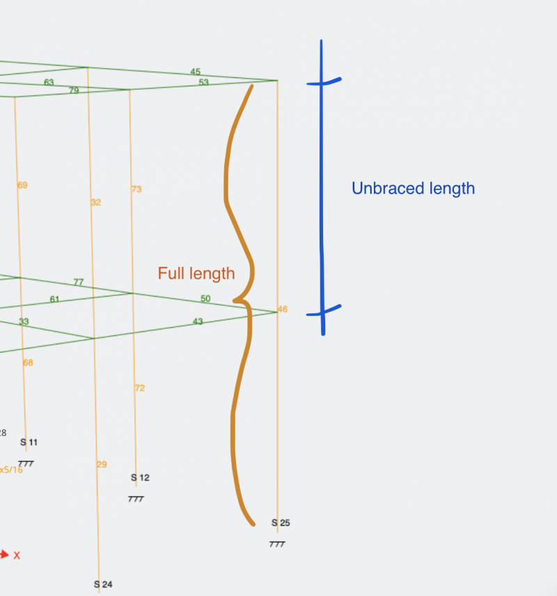
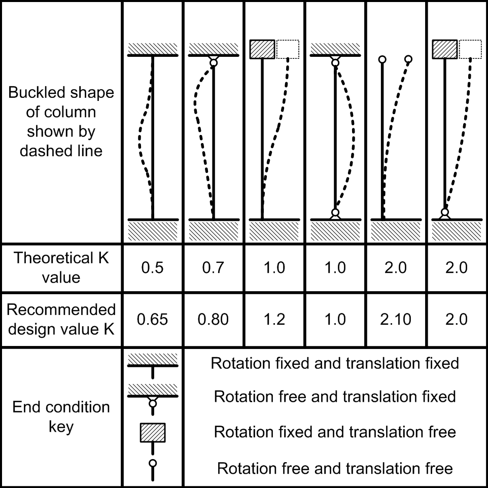
Guides To Effective Lengths Slenderness And K Determination The slenderness ratio is a quick and fairly simple ratio to calculate the buckling phenomena that occurs in a compression member. it is defined as: slenderness ratio = kl r. where k is the effective length factor, l is the unbraced length of the member and r is the radius of gyration. the product kl is known simply as the effective length. In place of the actual column length. the effective length factor k can be derived by performing a buckling anal ysis of the particular structure to determine the critical stress. the pinned end column with an equivalent length which gives the same critical stress establishes the k factor. the k factor, then, is just a way of providing.

Guides To Effective Lengths Slenderness And K Determination The significance of slenderness effect is expressed through slenderness ratio. 4.2 slenderness ratio the degree of slenderness in a column is expressed in terms of "slenderness ratio," defined below: slenderness ratio: rklu where, lu is unsupported column length; k is effective length factor reflecting the end restraint and. Suppose we now define the effective lengths of the upper and lower segments (kl\ and kl2) to be values such that at buckling, (10) (kl2y in terms of the root ztt of the characteristic equation, the effective lengths are kl\ — irl\ zrt ku = tu (ztt p) (11) these are the effective lengths that must be inserted into eqs. 7.2. design column boundary conditions in slenderness calculations when the slenderness effects for a non sway frame column is considered in creating a model using spcolumn, the effective length factor can be computed by defining the properties of the columns and beams connected to the top and bottom of the design column. The american concrete institute (aci) 318 11 permits the use of the moment magnifier method for computing the design ultimate strength of slender reinforced concrete columns that are part of braced frames. this computed strength is influenced by the column effective length factor k, the equivalent uniform bending moment diagram factor c m and the effective flexural stiffness ei among other.

Guides To Effective Lengths Slenderness And K Determination 7.2. design column boundary conditions in slenderness calculations when the slenderness effects for a non sway frame column is considered in creating a model using spcolumn, the effective length factor can be computed by defining the properties of the columns and beams connected to the top and bottom of the design column. The american concrete institute (aci) 318 11 permits the use of the moment magnifier method for computing the design ultimate strength of slender reinforced concrete columns that are part of braced frames. this computed strength is influenced by the column effective length factor k, the equivalent uniform bending moment diagram factor c m and the effective flexural stiffness ei among other. In p360, a simplified formula for the non dimensional slenderness of a doubly symmetric i section beam, taken from ncci sn0023 is given as: λ lt = ud λ z β w 1 1 the effective length factor for destabilising load is parameter d. the minor axis non dimensional slenderness λ z = λ z λ 1 and λ z = kl i z where k is an effective length. Defined effective length. the method gives a nominal second order moment based on a deflection, which in turn is based on the effective length and an estimated maximum curvature. cl 5.8.5, cl 5.8.8 5.6.2.1 (preferred in uk) actions effective length, l0 imperfections slenderness, λλλλ slenderness limit, λλλλlim is λλλλ ≥≥≥≥.

Guides To Effective Lengths Slenderness And K Determination In p360, a simplified formula for the non dimensional slenderness of a doubly symmetric i section beam, taken from ncci sn0023 is given as: λ lt = ud λ z β w 1 1 the effective length factor for destabilising load is parameter d. the minor axis non dimensional slenderness λ z = λ z λ 1 and λ z = kl i z where k is an effective length. Defined effective length. the method gives a nominal second order moment based on a deflection, which in turn is based on the effective length and an estimated maximum curvature. cl 5.8.5, cl 5.8.8 5.6.2.1 (preferred in uk) actions effective length, l0 imperfections slenderness, λλλλ slenderness limit, λλλλlim is λλλλ ≥≥≥≥.

Comments are closed.