Email Fb 46 Thermostat Wiring Diagram Thermostat Wiring Diagrams

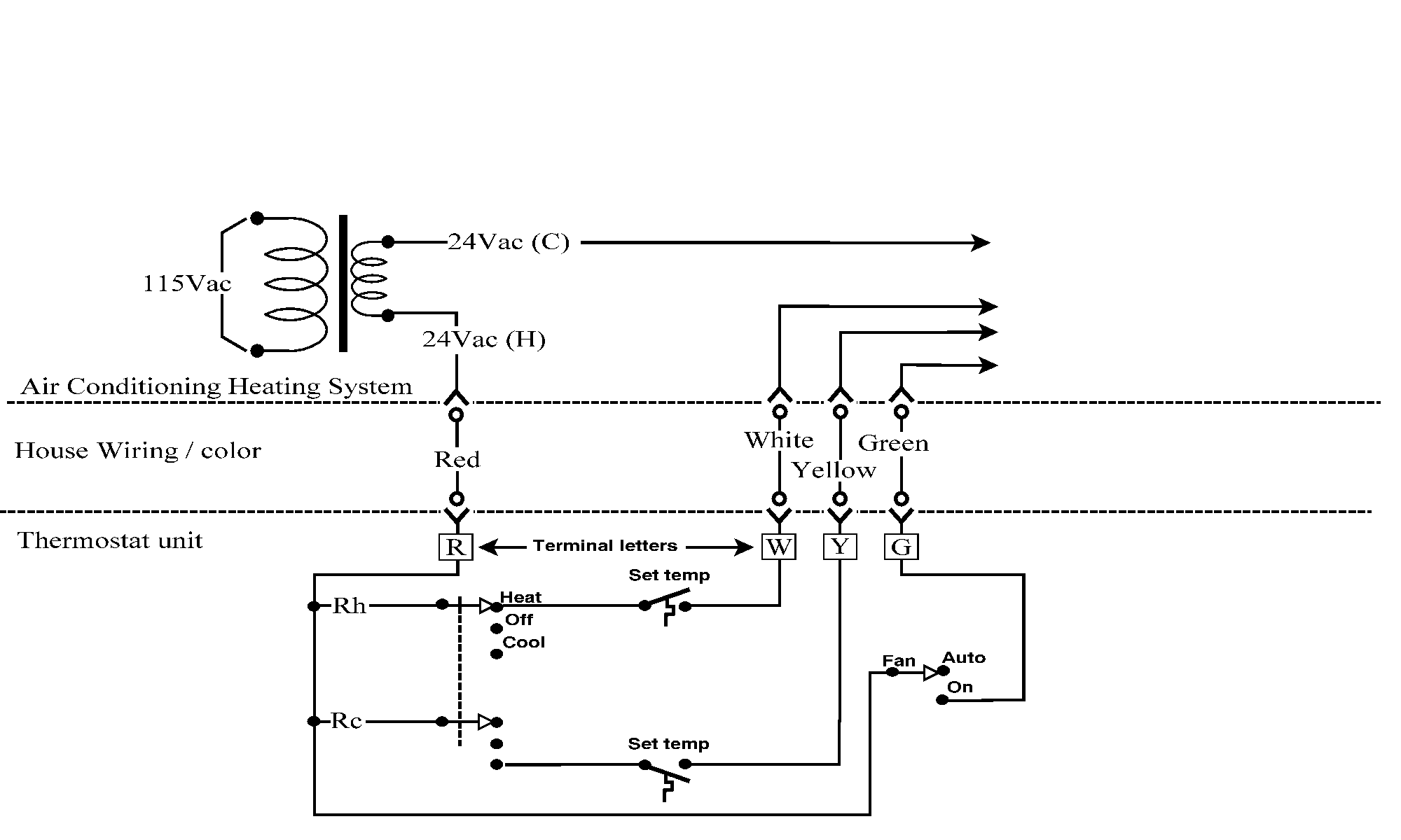
Email Fb 46 Thermostat Wiring Diagram Thermostat Wiring Diagrams Air conditioner thermostat wiring details and color code. r terminal is connected to the red wire or r wire this is 24 volt power for the thermostat and controlled devices. origin is the control transformer and then the r terminal. g terminal is connected to the green wire or g wire this is for the blower fan in the air handler. R or rc wire (power) connected to the r power terminal to power the thermostat. w wire (heat), connected to the heating control. g wire (fan) connected to the fan control to operate a blower in your hvac system. y1 wire (cooling) connected to the y terminal compressor refrigerant system.

Email Fb 46 Thermostat Wiring Diagram Thermostat Wiring Diagrams The hvac wiring diagram thermostat illustrates the electrical connections between the thermostat, the heating or cooling system, and the power supply. it shows the different wires and terminals involved in the system and their corresponding functions. the diagram provides a visual representation of how the thermostat interacts with the hvac. 8 wire thermostat wiring. here is the most common use of 8 wires. what uses 8 wire thermostat wiring? these are almost always heat pump hvac systems aux heat. how to wire an 8 wire thermostat: 1). attach the red wire to the r terminal for 24v power. 2). attach the white wire to the w (or w1) terminal for the heat pump’s heating mode. 3). The mechanical thermostat is a simple but effective device used to control the temperature in a heating or cooling system. it consists of a temperature sensor, a control switch, and a mercury filled bulb or bimetallic strip. when the temperature in the room reaches the desired level, the thermostat activates the switch, turning off the heating. Using a screwdriver, connect the wires according to the wiring diagram. most single pole thermostats have only two wires: one for the power supply and the other for controlling the heating system. make sure the wires are securely tightened to ensure a good connection. step 5: mount the thermostat.

How To Wire A Thermostat Diagram The mechanical thermostat is a simple but effective device used to control the temperature in a heating or cooling system. it consists of a temperature sensor, a control switch, and a mercury filled bulb or bimetallic strip. when the temperature in the room reaches the desired level, the thermostat activates the switch, turning off the heating. Using a screwdriver, connect the wires according to the wiring diagram. most single pole thermostats have only two wires: one for the power supply and the other for controlling the heating system. make sure the wires are securely tightened to ensure a good connection. step 5: mount the thermostat. Key wires: red (r) for power, white (w) for heating, and yellow (y) for cooling. process: connect the red wire to the r terminal, the white wire to the w terminal, and the yellow wire to the y terminal. if there’s a green wire for the fan, connect it to the g terminal. programmable thermostats:. G – green: this wire controls the blower motor in the furnace. y2 – light blue: this wire is necessary if you have a two stage ac compressor. if the ac is single stage, this terminal will be empty. w2 – light brown: this wire functions like the light blue wire but for furnaces with low and high stages of heating.

Comments are closed.