Dual Power Supply Circuit Electric Power Supplies

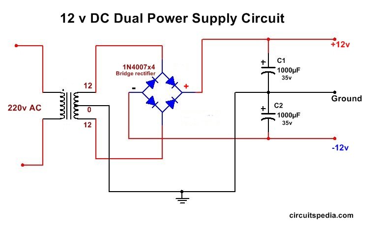
Dual Power Supply Circuit The voltage output range of a dual power supply typically spans from ±1.2v to ±30v or even higher, depending on the specific requirements of your electronic circuit. dual power supplies serve as a versatile source of power, allowing engineers and hobbyists to work with components and circuits that demand both positive and negative voltage levels. Published october 6, 2017 7. r ravi kansagara. author. 12v and 12v dual power supply circuit. the objective of this project is to convert 220v ac supply in to 12v and 12v dc supply, that is why it is named dual power supply as we get positive and negative 12v power supply at the same time. this can be achieved in simple three steps: firstly.

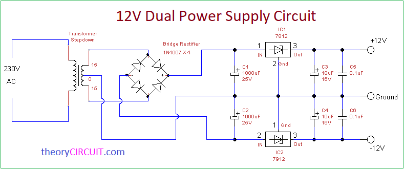
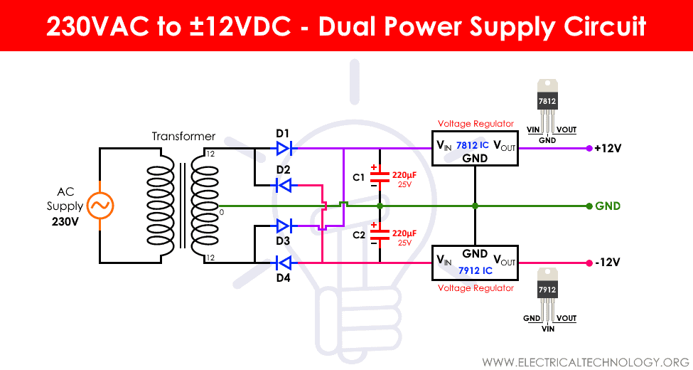
Dual Power Supply Circuit Diagram 230vac To в 12vdc This article helps you to built dual power supply circuit by using step down transformer and linear voltage regulators. most electronic circuit and application requires dc voltage range mostly falls in 5, 12 and 15 volts, hence three types of dual power supply circuit listed as, 5 volt ( 5v gnd 5v) 12 volt ( 12v gnd 12v) 15 volt ( 15v gnd 15v). 230 vac to ±12 vdc dual power supply circuit. as the name suggests, this circuit is designed to convert the mains supply voltage of around 220v ac into two voltages of 12v and 12v dc values. the specialty of this circuit is, we will get both the voltages at the same time. there are some particular applications where, a circuit requires a. The rectifier circuit is a converter, which converts ac supply into dc supply. it is generally made up of diode switches. in this dual power supply circuit, the diode bridge rectifier is made up of four power diodes. low voltage ac supply from the secondary winding of the transformer is fed into the bridge rectifier module (1n4007 x 4), the. For a quick and simple dual power supply, use two resistors in series connected in parallel with two capacitors. connect the two ends to the battery or power source and bam! you have a dual power supply. typical values for bipolar converters like this are 100k 1m for the resistors and 47uf to 4700uf depending on the current draw of your circuit.

Dual Voltage Power Supply Circuit Diagram The rectifier circuit is a converter, which converts ac supply into dc supply. it is generally made up of diode switches. in this dual power supply circuit, the diode bridge rectifier is made up of four power diodes. low voltage ac supply from the secondary winding of the transformer is fed into the bridge rectifier module (1n4007 x 4), the. For a quick and simple dual power supply, use two resistors in series connected in parallel with two capacitors. connect the two ends to the battery or power source and bam! you have a dual power supply. typical values for bipolar converters like this are 100k 1m for the resistors and 47uf to 4700uf depending on the current draw of your circuit. Dual power supplies are circuits that generate two different output voltages from a single input source. there are numerous types and configurations possible. the most common configuration provides two different positive dc voltage outputs or two equal magnitude and opposite polarity dc voltage outputs. for circuits that combine digital control. This is the circuit diagram of a dual adjustable power supply using ic’s lm 317 & lm 337. lm317 is able to deliver a maximum of 1.5 a at a range of 1.2 v to 30v. lm317 is a positive voltage regulator and lm337 is the negative compliment voltage regulator ic of lm317. the lm317 ic is a 3 terminal voltage regulator that is designed to supply.

Comments are closed.