Composite Beam Design Overview

Steel And Composite Beam Design Overview Beam spacing on one side; b 1 = 10.000 ft. beam spacing on the other side; b 2 = 10.000 ft. deck orientation; deck ribs perpendicular to beam. profiles are assumed to meet all dimensional criteria in aisc 360 16. overall depth of slab; t = 6.000 in. height of ribs; h r = 1.500 in. centers of ribs; rib ccs = 6.000 in. Overview. composite beams are designed using a set of design forces obtained from 3d analysis. (grillage chasedown analysis and fe chasedown analysis results are not required.) the beams must be simply supported, single span unpropped structural steel beams. composite sections formed from hollow rolled sections,.

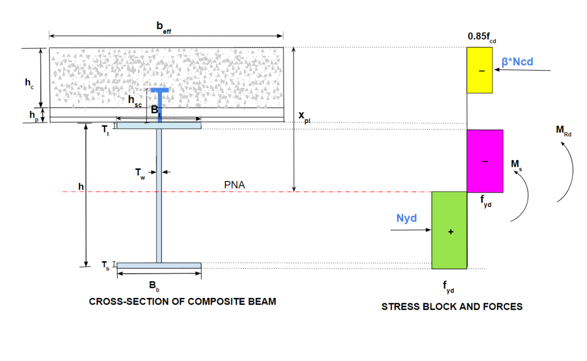
Steel And Composite Beam Design Overview Asdip Software Composite beam design as per ansi aisc 360 16 when it comes to the non residential multistorey building structures, composite construction is preferred over purely steel or rcc construction. the key of efficiency of composite construction over the other constructions can be expressed in a simple way. steel is good in tension and concrete is good in compression. Composite beam 2 43 . 2.16.1 composite beam segments 2 44 . 2.16.2 how the program distributes steel headed stud anchors on a beam 2 47 . 2.16.3 a note about multiple design load combinations 2 53 . 2.17 number of shear studs that fit in a composite beam segment 2 55 . 2.17.1 solid slab or deck ribs oriented parallel to beam span 2 55. Edition 2.0 february 2001 simply supported composite beams db1.1–1 design of simply supported composite beams for strength 1. scope and general 1.1 scope the strength design method in section 6 of australian standard as 2327.1−1996, composite structures, part 1: simply supported beams [1] is addressed in this design booklet. Designing the composite beam for strength criteria involves calculation of moment capacity. the module is capable of evaluating the sagging moment capacity of a beam as a case of simply supported beam. as a part of fsc, 3 different cases for the plastic neutral axis (pna) positioning are considered for evaluation of moment capacity.

Composite Beam Design Overview Youtube Edition 2.0 february 2001 simply supported composite beams db1.1–1 design of simply supported composite beams for strength 1. scope and general 1.1 scope the strength design method in section 6 of australian standard as 2327.1−1996, composite structures, part 1: simply supported beams [1] is addressed in this design booklet. Designing the composite beam for strength criteria involves calculation of moment capacity. the module is capable of evaluating the sagging moment capacity of a beam as a case of simply supported beam. as a part of fsc, 3 different cases for the plastic neutral axis (pna) positioning are considered for evaluation of moment capacity. Composite beam overview. tekla structural designer 2020. composite beams are designed using a set of design forces obtained from 3d analysis. (grillage chasedown analysis and fe chasedown analysis results are not required.) the beams must be simply supported, single span unpropped structural steel beams. the following are beyond scope:. 3.2 elastic behavior of composite beams 3.3 shear connectors 3.4 moment of resistance of composite beams for sagging moment (is: 11384) 3.5 moment of resistance of composite beams for hogging moment 3.6 worked out examples for composite beams chapter 4.0 design of composite columns 4.1 general design philosophy 4.2 short compression members 4.3.

Walkthrough Of A Composite Beam Design Skyciv Engineering Composite beam overview. tekla structural designer 2020. composite beams are designed using a set of design forces obtained from 3d analysis. (grillage chasedown analysis and fe chasedown analysis results are not required.) the beams must be simply supported, single span unpropped structural steel beams. the following are beyond scope:. 3.2 elastic behavior of composite beams 3.3 shear connectors 3.4 moment of resistance of composite beams for sagging moment (is: 11384) 3.5 moment of resistance of composite beams for hogging moment 3.6 worked out examples for composite beams chapter 4.0 design of composite columns 4.1 general design philosophy 4.2 short compression members 4.3.

Comments are closed.