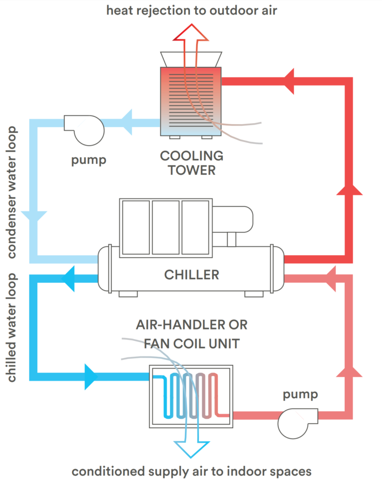
Chilled Water Schematic Diagram

How A Chilled Water System Works Hvac Training Shop Chilled water schematic and condenser water schematic, how to read and understand the engineering drawings with real world examples, illustrations, animations and video tutorial. covering chillers, pump sets, ahus, risers, primary and secondary systems, cooling towers and bypass lines. The chilled water supply and return to and from ahus and fcus are typically not included as the piping to these destinations is long and complicated. 3) chilled water network piping. further to the district cooling system diagram, the chilled water supply return to from ahus and fcus is included in what is known as a network piping diagram.

Chilled Water System Schematic Diagram Pdf The chilled water schematic diagram is a visual representation of the components and flow of a chilled water system. it provides an overview of how the system works and allows engineers and technicians to understand how the different parts of the system are connected and interact with each other. the schematic diagram typically starts with a. A chiller is made up of the 4 major components required for the refrigeration process which are: a) compressor, b) condenser, c) evaporator and d) expansion valve. to produce chilled water, the refrigerant absorbs heat from the water and thus, chilling the water to about 6.7°c (44°f). Sure setpoint or chilled water setpoint.select chiller for 2 to 4°f lower supply chilled water temperature than the cooling coils, to allow supply temperature reduction compensation for. irside low Δt or increased system load.install pressure independent cooling coil control valves to preserve system. The schematic diagram serves as a useful tool for understanding the system’s layout and functioning, allowing for easier troubleshooting and maintenance. chilled water system schematic diagram. a chilled water system is a central cooling system used to cool and dehumidify air in buildings and industrial complexes.

Schematic Of A Typical Chilled Water System Download Scientific Diagram Sure setpoint or chilled water setpoint.select chiller for 2 to 4°f lower supply chilled water temperature than the cooling coils, to allow supply temperature reduction compensation for. irside low Δt or increased system load.install pressure independent cooling coil control valves to preserve system. The schematic diagram serves as a useful tool for understanding the system’s layout and functioning, allowing for easier troubleshooting and maintenance. chilled water system schematic diagram. a chilled water system is a central cooling system used to cool and dehumidify air in buildings and industrial complexes. A chilled water piping schematic is a detailed diagram that shows the flow of chilled water through the system. it includes information about pipe sizes, valve locations, pump configurations, and other important components. this schematic is typically used by engineers, contractors, and hvac technicians to understand how the system is designed. The chilled water schematic diagram begins with the chiller, which is the central component of the system. the chiller cools the water using a refrigeration cycle, and then pumps it through the piping to the different loads. the diagram shows the connection points of the chilled water supply and return lines to the chiller.

Chilled Water Schematic Diagram A chilled water piping schematic is a detailed diagram that shows the flow of chilled water through the system. it includes information about pipe sizes, valve locations, pump configurations, and other important components. this schematic is typically used by engineers, contractors, and hvac technicians to understand how the system is designed. The chilled water schematic diagram begins with the chiller, which is the central component of the system. the chiller cools the water using a refrigeration cycle, and then pumps it through the piping to the different loads. the diagram shows the connection points of the chilled water supply and return lines to the chiller.

Comments are closed.