7812 And 7912 Dual Regulator Circuit With Explanation Electronic

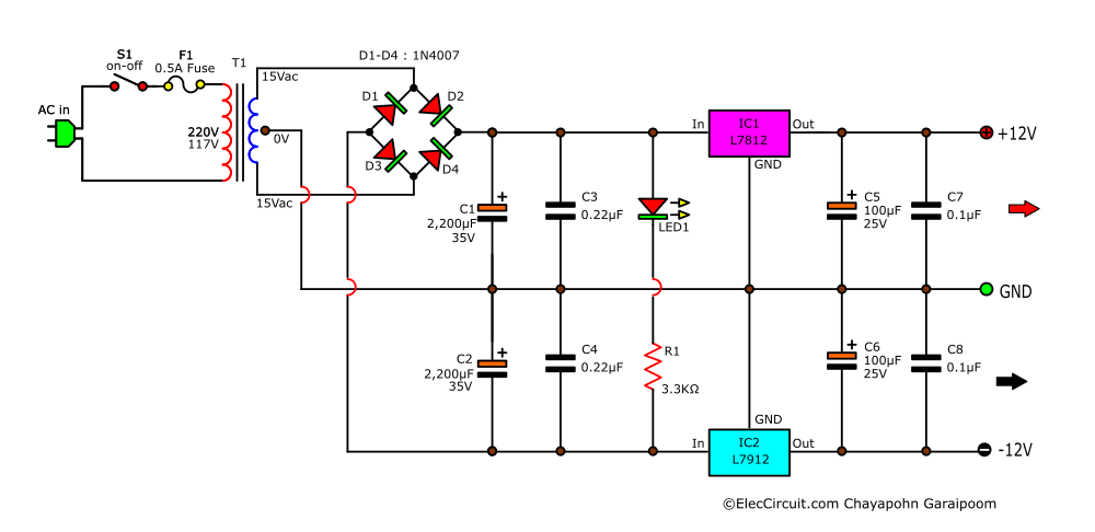
7812 And 7912 Dual Regulator Circuit With Explanation Electronic This is a 12v dual power supply circuit diagram using 7812 and 7912. we use an lm7812 voltage regulator ic for 12v and lm7912 for 12v. this circuit is suitable for a preamplifier tone control with an op amp circuit. it can deliver an output current of not more than 1a. i will show you, an interesting concept. Nov 12, 2023. this schematic depicts a 12v dual power supply circuit employing the lm7812 voltage regulator ic for 12v and the lm7912 for 12v. tailored for a preamplifier tone control with.

Dual Power Circuit Using 7812 7912 Voltage Regulators For Analog 5) after that solder the voltage regulator ics on the veroboard. 6) solder the 10uf capacitors on the veroboard. 7) solder the output terminal block connector on the veroboard. 8) connect the 240v to 15v ct transfomer with the input terminal block connector. 9) power up and test the circuit using a 220v wall outlet. circuit diagram working. The circuit diagram given beneath is a regulated 12 v dual power supply circuit utilizing two voltage regulator ics lm7812 and lm7912. both the ics are from the arrangement of lm78xx and lm79xx voltage controllers accessible in the to 92 transistor bundle. these ics are worked to perform step down dc to dc converter errands in electronic. Lastly, the output of the capacitor that is pure dc is given to voltage regulator ic 7812 and ic7912 which will regulate the output voltage at 12v and 12v dc, despite the change in input voltage. required components: centre tapped transformer (220v 12v) power diodes (6a) – 4no. capacitor (2200μf, 25v) – 2no. voltage regulator (ic 7812 & 7912). The dual power supply of ±12v is shown below using positive ic regulator 7812 and negative ic regulator 7912. the input capacitors prevent the oscillations. the output capacitors improve the transient response. the diode d1 and d2 protect the regulator against the short circuit at the input terminals. the diodes d3 and d4 protect the circuit.
7912 Voltage Regulator Circuit Diagram Lastly, the output of the capacitor that is pure dc is given to voltage regulator ic 7812 and ic7912 which will regulate the output voltage at 12v and 12v dc, despite the change in input voltage. required components: centre tapped transformer (220v 12v) power diodes (6a) – 4no. capacitor (2200μf, 25v) – 2no. voltage regulator (ic 7812 & 7912). The dual power supply of ±12v is shown below using positive ic regulator 7812 and negative ic regulator 7912. the input capacitors prevent the oscillations. the output capacitors improve the transient response. the diode d1 and d2 protect the regulator against the short circuit at the input terminals. the diodes d3 and d4 protect the circuit. The voltage regulators used in this circuit are 7812 and 7912. these are the voltage regulators which produce both positive and negative polarity dc voltages of 12v. applications of dual power supply circuit. op amps need two power sources, one is positive and another is negative. an op amps circuit can be powered using a dual power supply circuit. The circuit given here is of a regulated dual power supply that provides 12v and 12v from the ac mains. a power supply like this is a very essential tool on the work bench of an electronic hobbyist. the transformer t1 steps down the ac mains voltage and diodes d1, d2, d3 and d4 does the job of rectification. capacitors c1 and c2 does the job.

12v Dual Power Supply Using 7812 7912 Eleccircuit The voltage regulators used in this circuit are 7812 and 7912. these are the voltage regulators which produce both positive and negative polarity dc voltages of 12v. applications of dual power supply circuit. op amps need two power sources, one is positive and another is negative. an op amps circuit can be powered using a dual power supply circuit. The circuit given here is of a regulated dual power supply that provides 12v and 12v from the ac mains. a power supply like this is a very essential tool on the work bench of an electronic hobbyist. the transformer t1 steps down the ac mains voltage and diodes d1, d2, d3 and d4 does the job of rectification. capacitors c1 and c2 does the job.

Comments are closed.